Milestone 4
Treasure Detection
Objective
The goal of this milestone is to fully implement the image processor so it can detect whether or not there is a treasure, what color the treasure is, and what shape the treasure is.
Implementation
To implement the image processor, we expanded our basic image processor from lab 4. At the end of lab 4, we were able to detect whether or not there is a treasure and what color the treasure was. Here is the video of treasure detection and color detection from lab 4. To determine the shape, we took pixels from the top, middle and bottom of the image and pixels from the left, center, and right of the image. We compared these pixels to eachother to determine the shape. To get these pixels, we divided the screen into a grid like so, and incremented a counter if the pixel was in that section. To find the size of the sections, we divided the screen width and height by 3, as seen in this image.
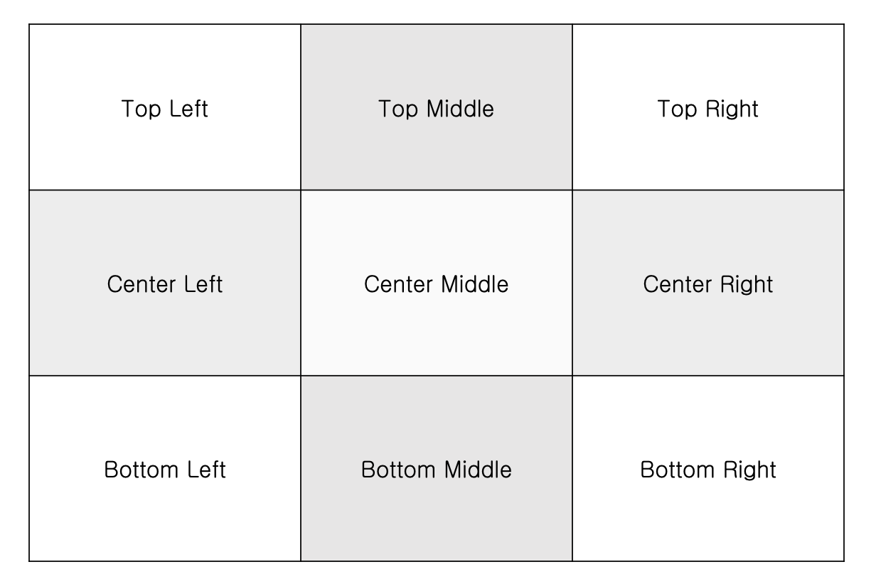
Figure 1: Sections of the Screen
Here is the code that updates the counters respective to the location on the grid:
			RESULT = RESULT;
			if (PIXEL_IN[7:6] > PIXEL_IN[1:0] && PIXEL_IN[7:6] > PIXEL_IN[4:3]) begin
				REDCOUNT = REDCOUNT + 1'b1;
			end
			else if (PIXEL_IN[1:0] > PIXEL_IN[7:6] && PIXEL_IN[1:0] >= PIXEL_IN[4:3]) begin
				BLUECOUNT = BLUECOUNT + 1'b1;
			end
			REDCOUNTTEMP = REDCOUNT;
			BLUECOUNTTEMP = BLUECOUNT;
			if (VGA_PIXEL_Y == 10'd50 && (VGA_PIXEL_X>=10'd48 && VGA_PIXEL_X<=10'd128))begin
				if (PIXEL_IN[7:6] > PIXEL_IN[1:0] && PIXEL_IN[7:6] > PIXEL_IN[4:3]) begin
					REDCOUNTTOP = REDCOUNTTOP + 1'b1;
				end
				else if (PIXEL_IN[1:0] > PIXEL_IN[7:6] && PIXEL_IN[1:0] >= PIXEL_IN[4:3]) begin
					BLUECOUNTTOP = BLUECOUNTTOP + 1'b1;
				end
				REDCOUNTTEMPTOP = REDCOUNTTOP;
				BLUECOUNTTEMPTOP = BLUECOUNTTOP;
			end
			else if (VGA_PIXEL_Y == 10'd60 && (VGA_PIXEL_X>=10'd48 && VGA_PIXEL_X<=10'd128))begin
				if (PIXEL_IN[7:6] > PIXEL_IN[1:0] && PIXEL_IN[7:6] > PIXEL_IN[4:3]) begin
					REDCOUNTTOPMID = REDCOUNTTOPMID + 1'b1;
				end
				else if (PIXEL_IN[1:0] > PIXEL_IN[7:6] && PIXEL_IN[1:0] >= PIXEL_IN[4:3]) begin
					BLUECOUNTTOPMID = BLUECOUNTTOPMID + 1'b1;
				end
				REDCOUNTTEMPTOPMID = REDCOUNTTOPMID;
				BLUECOUNTTEMPTOPMID = BLUECOUNTTOPMID;
			end
			else if (VGA_PIXEL_Y == 10'd72 && (VGA_PIXEL_X>=10'd48 && VGA_PIXEL_X<=10'd128)) begin
				if (PIXEL_IN[7:6] > PIXEL_IN[1:0] && PIXEL_IN[7:6] > PIXEL_IN[4:3]) begin
					REDCOUNTMID = REDCOUNTMID + 1'b1;
				end
				else if (PIXEL_IN[1:0] > PIXEL_IN[7:6] && PIXEL_IN[1:0] >= PIXEL_IN[4:3]) begin
					BLUECOUNTMID = BLUECOUNTMID + 1'b1;
				end
				REDCOUNTTEMPMID = REDCOUNTMID;
				BLUECOUNTTEMPMID = BLUECOUNTMID;
			end
			else if (VGA_PIXEL_Y == 10'd84 && (VGA_PIXEL_X>=10'd48 && VGA_PIXEL_X<=10'd128)) begin
				if (PIXEL_IN[7:6] > PIXEL_IN[1:0] && PIXEL_IN[7:6] > PIXEL_IN[4:3]) begin
					REDCOUNTBOTMID = REDCOUNTBOTMID + 1'b1;
				end
				else if (PIXEL_IN[1:0] > PIXEL_IN[7:6] && PIXEL_IN[1:0] >= PIXEL_IN[4:3]) begin
					BLUECOUNTBOTMID = BLUECOUNTBOTMID + 1'b1;
				end
				REDCOUNTTEMPBOTMID = REDCOUNTBOTMID;
				BLUECOUNTTEMPBOTMID = BLUECOUNTBOTMID;
			end
			else if (VGA_PIXEL_Y == 10'd94 && (VGA_PIXEL_X>=10'd48 && VGA_PIXEL_X<=10'd128)) begin
				if (PIXEL_IN[7:6] > PIXEL_IN[1:0] && PIXEL_IN[7:6] > PIXEL_IN[4:3]) begin
					REDCOUNTBOTTOM = REDCOUNTBOTTOM + 1'b1;
				end
				else if (PIXEL_IN[1:0] > PIXEL_IN[7:6] && PIXEL_IN[1:0] >= PIXEL_IN[4:3]) begin
					BLUECOUNTBOTTOM = BLUECOUNTBOTTOM + 1'b1;
				end
				REDCOUNTTEMPBOTTOM = REDCOUNTBOTTOM;
				BLUECOUNTTEMPBOTTOM = BLUECOUNTBOTTOM;
			end
Once we had all the values stored, on the posedge of CLK and the negedge of VGA_VSYNC_NEG, we check the values of each of the counters to eachother and a threshold to determine the color and shape. We used these sections to tell what shape it is. The black dots in this image represent the locations that we took to determine what the shape was.
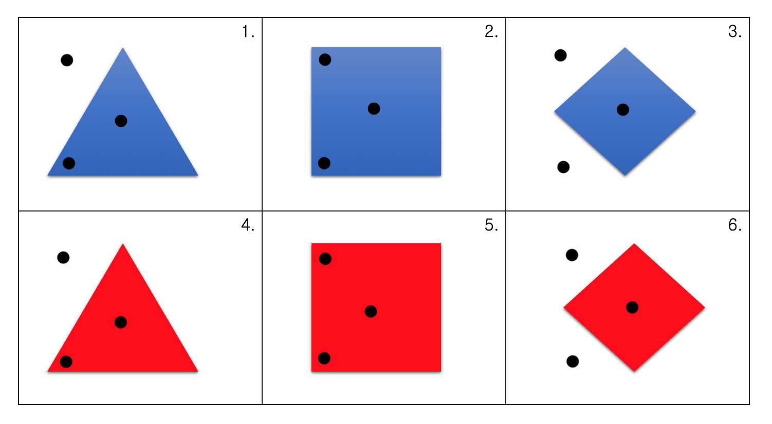
Figure 2: Shapes and Colors
We also changed the way result is updated from lab 4. Since we now need to take into account the shape, we made result a 3 bit number, with the following values:
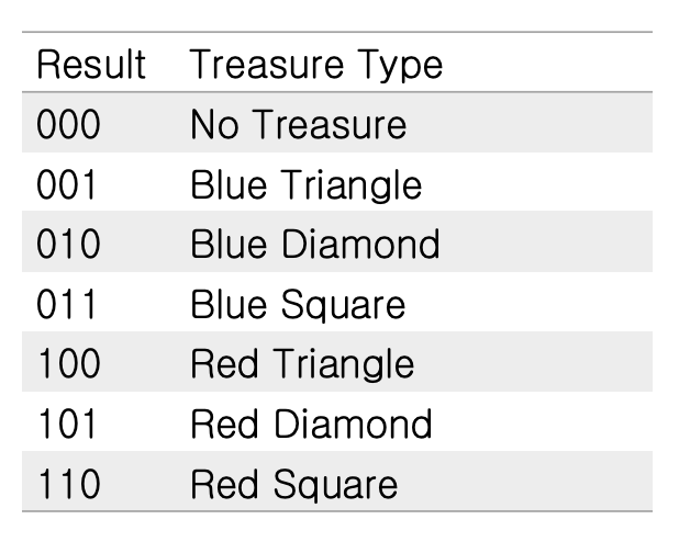
Figure 3: Value of variable RESULT
Here is our updated code:
always @ (posedge CLK, negedge VGA_VSYNC_NEG) begin
		if (!VGA_VSYNC_NEG) begin
			if ((BLUECOUNTTEMP) > (REDCOUNTTEMP) && (BLUECOUNTTEMP) > 16'd17000) begin
				if (BLUECOUNTTEMPTOPMID>BLUECOUNTTEMPTOP && BLUECOUNTTEMPMID>BLUECOUNTTEMPTOPMID && BLUECOUNTTEMPBOTMID>BLUECOUNTTEMPMID && BLUECOUNTTEMPBOTTOM>BLUECOUNTTEMPBOTMID) begin //&& BLUECOUNTTEMPTOP<BLUECOUNTTEMPBOTTOM BLUECOUNTTEMPTOPMID>BLUECOUNTTEMPTOP &&
					RESULT = 3'b001; //blue triangle
				end
				else if (BLUECOUNTTEMPTOP<BLUECOUNTTEMPTOPMID && BLUECOUNTTEMPTOP<BLUECOUNTTEMPMID && BLUECOUNTTEMPBOTTOM<BLUECOUNTTEMPMID && BLUECOUNTTEMPBOTTOM<BLUECOUNTTEMPBOTMID) begin
					RESULT = 3'b010; //blue diamond
				end
				else begin
					RESULT = 3'b011; //blue square
				end
			end
			else if ((REDCOUNTTEMP) > (BLUECOUNTTEMP) && (REDCOUNTTEMP) > 16'd17000) begin //17000 is arbitrary, can change
				if (REDCOUNTTEMPTOPMID>REDCOUNTTEMPTOP && REDCOUNTTEMPMID>REDCOUNTTEMPTOPMID && REDCOUNTTEMPBOTMID>REDCOUNTTEMPMID && REDCOUNTTEMPBOTTOM>REDCOUNTTEMPBOTMID) begin //&& REDCOUNTTEMPTOP<REDCOUNTTEMPBOTTOM
					RESULT = 3'b100; //red triangle
				end
				else if (REDCOUNTTEMPTOP<REDCOUNTTEMPTOPMID && REDCOUNTTEMPTOP<REDCOUNTTEMPMID && REDCOUNTTEMPBOTTOM<REDCOUNTTEMPMID && REDCOUNTTEMPBOTTOM<REDCOUNTTEMPBOTMID) begin
					RESULT = 3'b101; //red diamond
				end
				else begin
					RESULT = 3'b110; //red square
				end
			end
			else begin
				RESULT = 3'b000; //no color detected
			end
At the end of this always block, we set all the counters to 0 so that they reset for the next image.
One issue we encountered was that we could not write directly to the registers because the code would not compile. To fix this, we used temporary registers to store the value of the pixel and then we transferred these values to the actual registers.
Once we updated the image processing code in Verilog, we needed to connect the result to the Arduino. We connected the GPIO pins to the Arduino pins in the same manner as lab 4. Then, we updated our Arduino code to account for the shape detection. We created variables for every shape so that if the shape was detected, we would increment the respective counter and set the other counters to 0. We would then compare these values to a threshold, and if it is above the threshold, a shape is detected. If none of the counters are above the threshold, then there is no treasure. For testing purposes, we printed the type of treasure to the serial monitor. Here is our updated Arduino code:
void loop(){
  MSB = digitalRead(11);
  mid = digitalRead(10);
  LSB = digitalRead(9);

  if(MSB == HIGH && mid == LOW && LSB == LOW){
    redTriangle++;
    redSquare = 0;
    redDiamond = 0;
    blueSquare = 0;
    blueTriangle = 0;
    blueDiamond = 0;
  }
  else if(MSB == HIGH && mid == LOW && LSB == HIGH){
    redDiamond++;
    redTriangle = 0;
    redSquare = 0;
    blueSquare = 0;
    blueTriangle = 0;
    blueDiamond = 0;
  }
  else if(MSB == HIGH && mid == HIGH && LSB == LOW){
    redSquare++;
    redDiamond = 0;
    redTriangle = 0;
    blueSquare = 0;
    blueTriangle = 0;
    blueDiamond = 0;
  }
  else if(MSB == LOW && mid == LOW && LSB == HIGH){
    blueTriangle++;
    redSquare = 0;
    redTriangle = 0;
    redDiamond = 0;
    blueSquare = 0;
    blueDiamond = 0;
  }
  else if(MSB == LOW && mid == HIGH && LSB == HIGH){
    blueSquare++;
    redSquare = 0;
    redTriangle = 0;
    redDiamond = 0;
    blueTriangle = 0;
    blueDiamond = 0;
  }
  else if(MSB == LOW && mid == HIGH && LSB == LOW){
    blueDiamond++;
    redSquare = 0;
    redTriangle = 0;
    redDiamond = 0;
    blueSquare = 0;
    blueTriangle = 0;
  }
  else { //nothing
    Serial.println("No Treasure");
    redSquare = 0;
    redTriangle = 0;
    redDiamond = 0;
    blueSquare = 0;
    blueTriangle = 0;
    blueDiamond = 0;
  }
Image processor with a red triangle, red square, red diamond, blue triangle, blue square, and blue diamond: