Milestone 2
Wall and Robot Detection
Objective
The goal of this milestone is to successfully detect walls and other robots and implement this into our full system.
Wall Detection
We added a distance sensor to our robot to detect the walls. The distance sensor connects to ground and 5V and outputs an analog signal.
To determine the threshold, we looked at the analog signal when the sensor was near the wall and when it was farther away from the wall. When a wall was detected, we turned on a green LED (which is in pin 8) and had the robot turn left to use right hand wall following. The code is as follows:
wallval = analogRead(A3);

  if(waitingcommand == 1){
    if(wallval >= 200){
      turncommand = 1;
    }
    else {
      turncommand = 2;
    }
    waitingcommand = 0;
    digitalWrite(8, HIGH);
  }

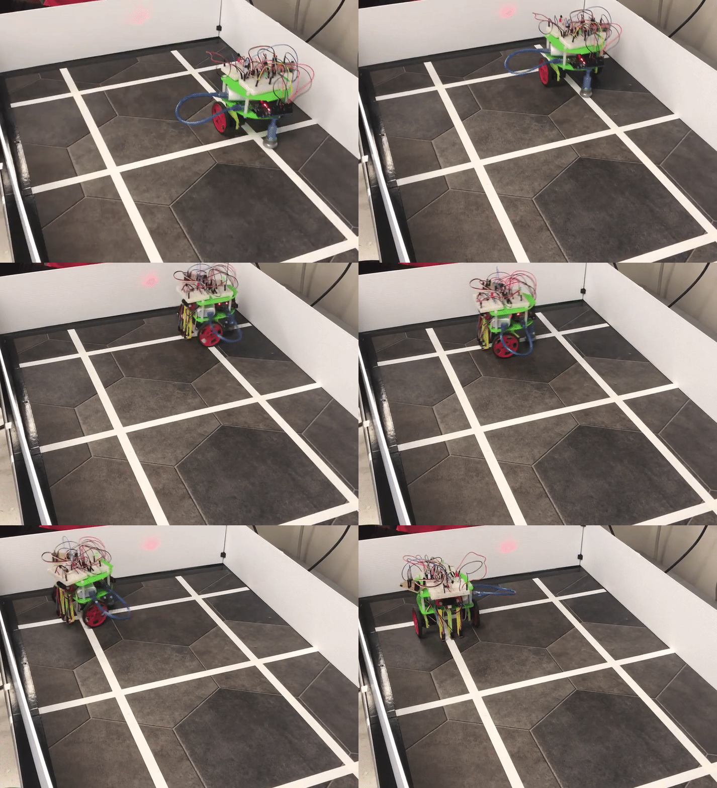
Following an arbitrary set of walls through right-hand wall following.
Robot Detection
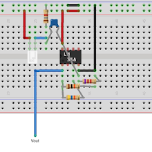
For the robot detection, we used the IR amplifier circuit from lab 2.

Amplifier schematic.
We decided for our robot to stop when another robot is detected. To do this, we added on to the code from lab 2 and set both servos to 90. We also added a red LED on our robot to indicate when another robot is detected (pin 2).
if(fft_log_out[42] >= 55){

      robotkill++;
    }
    else{

      robotkill = 0;
    }
    digitalWrite(2, LOW);
    if(robotkill > 10){
      wheelRight.write(90);
      wheelLeft.write(90);
      digitalWrite(2, HIGH);
      while(1);
    }
}
In the future, we may want to implement another strategy, potentially a more offensive strategy, for when another robot is detected.
Full System
To implement the full system, we needed to fix the timing because the servos and the FFT use the same timer. The inital problem was that the FFT function needed to change values of multiple registers, but these registers were also used for some of our line following functions. To fix this, we had to assign temporary values to the registers used in the FFT library, and only change those values when FFT was running:
void doFFT() {
  byte temp_TIMSK0 = TIMSK0; // save register values to avoid turning timer off completely
  byte temp_ADCSRA = ADCSRA;
  byte temp_ADMUX = ADMUX;

  /* FROM robotsense_ir */
  TIMSK0 = 0; // turn off timer0 for lower jitter
  ADCSRA = 0xe5; // set the adc to free running mode
  ADMUX = 0x40; // use adc0
  ADMUX = 0x01; // turn off the digital input for adc0

  cli();  // UDRE interrupt slows this way down on arduino1.0
    for (int i = 0 ; i < 512 ; i += 2) { // save 256 samples
      while(!(ADCSRA & 0x10)); // wait for adc to be ready
      ADCSRA = 0xf5; // restart adc
      byte m = ADCL; // fetch adc data
      byte j = ADCH;
      int k = (j << 8) | m; // form into an int
      k -= 0x0200; // form into a signed int
      k <<= 6; // form into a 16b signed int
      fft_input[i] = k; // put real data into even bins
      fft_input[i+1] = 0; // set odd bins to 0
    }
    fft_window(); // window the data for better frequency response
    fft_reorder(); // reorder the data before doing the fft
    fft_run(); // process the data in the fft
    fft_mag_log(); // take the output of the fft
    sei();
    if(fft_log_out[42] >= 45){
      digitalWrite(LED_BUILTIN, HIGH);
    }
    else{
      digitalWrite(LED_BUILTIN, LOW);
    }


  TIMSK0 = temp_TIMSK0;
  ADCSRA = temp_ADCSRA;
  ADMUX = temp_ADMUX;

}
We then added this function to our line tracking code, as well as the wall detection code and the robot detection code to implement the full system.
void loop()
{
  wallval = analogRead(A3);

  if(waitingcommand == 1){
    if(wallval >= 200){
      turncommand = 1;
    }
    else {
      turncommand = 2;
    }
    waitingcommand = 0;
    digitalWrite(8, HIGH);
  }

  correctionMachine();

  doFFT();
  Serial.println(wallval);
  /*
  e_p = desiredPos - linePos; //find proportional error term
  e_d = e_p - prev_e_p; //find first derivative error term
  prev_e_p = e_p;
  if((e_p + e_d) > 0){
    correctLeft();
  }
  else if((e_p + e_d) < 0){
    correctRight();
  }
  */
  wheelRight.write(rightspeed);
  wheelLeft.write(leftspeed);
  delay(5);
}
Robot doing line tracking, wall detection, and robot detection. The green LED indicates detection of walls, and the red LED indicates detection of other robots: