Milestone 1
Figure Eight
Objective
The main goal of this milestone is to have the robot follow a line and to have the robot successfully traverse the grid in a figure eight.
Integrating Sensors and Following a Line
We decided to use three QTR-1 line sensors to have our robot detect a line on the ground. The line sensors were placed in line next to each other, about one centimeter apart.

Robot with three line sensors in the front.
Since the line sensors are infrared sensors that record greyscale values from 0 to 1000, we set our threshold value to be 400 to tell when the sensor is on or off the line. Line sensors that outputted values less than 400 were on the line, and line sensors that outputted values greater than or equal to 400 were off the line.
The line sensors were able to detect if the robot was on the line based off of the following diagram:
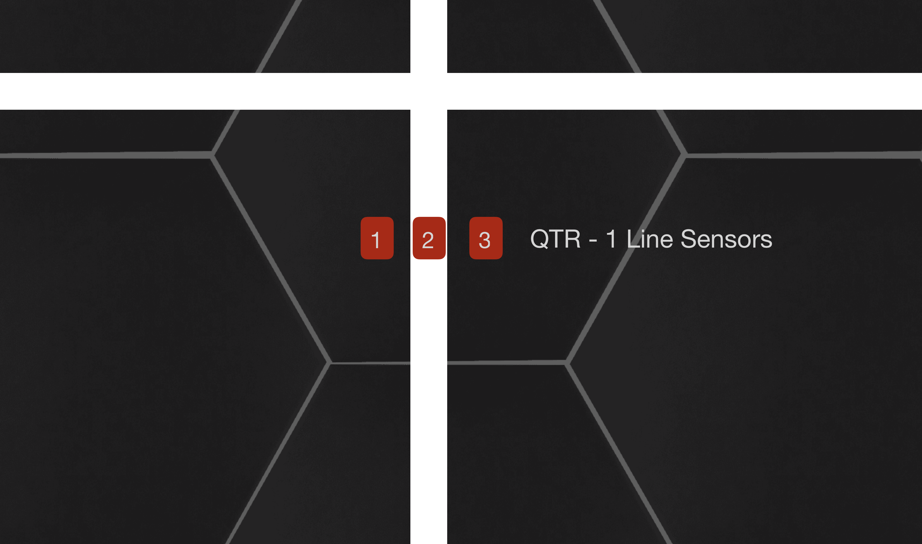
Diagram of placement of line sensors relative to white line.
We had our robot detect and follow the line based using the following logic:
- Case 1: If the middle sensor outputted a value less than the threshold (sensor on line) and the left and right sensors outputted values greater than the threshold (sensors off line), then the robot was straight on the line and could move forwards.
- Case 2: If the right sensor outputted a value less than the threshold (sensor on line) and the middle and left sensors outputted values greater than the threshold (sensors off line), then the robot was aligned too far to the left, and small corrections needed to be made to recenter the robot on the line.
- Case 3: If the left sensor outputted a value less than the threshold (sensor on line) and the middle and right sensors outputted values greater than the threshold (sensors off line), then the robot was aligned too far to the right, and small corrections needed to be made to recenter the robot on the line.
- Case 4: If all three sensors outputted values less than the threshold, then the robot had reached an intersection.
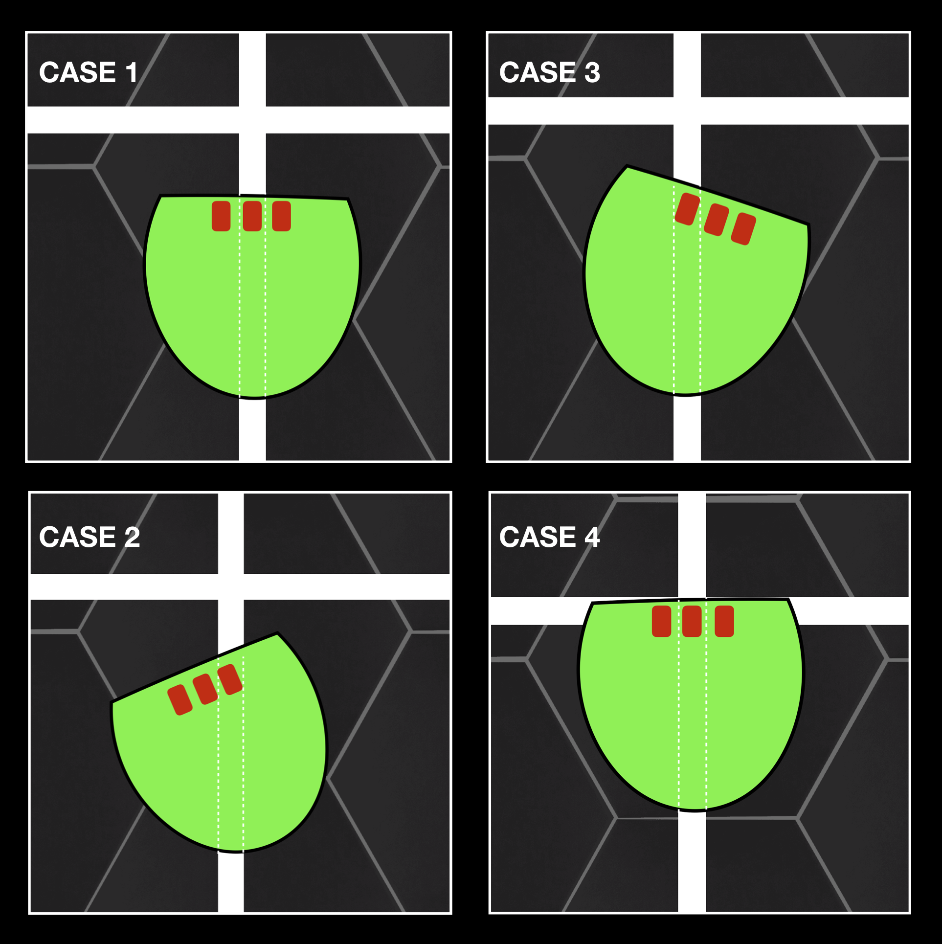
Four cases to have the robot follow the line.
Understanding these cases eased us into writing code to make the robot follow a line:
...
void moveForwards() {
  while (!reachedCross()) {
    if (correctionsNeeded()) {
     correct();
    }
    wheelRight.write(0);
    wheelLeft.write(180);
  }
  //halt();
}

boolean reachedCross() {
  qtra.read(sensorValues);
  if (sensorValues[1] < threshold && sensorValues[2] < threshold) {
    return true;
  }
  else{
    return false;
  }
}

void correct() {
  if (sensorValues[1] < threshold) {
    wheelRight.write(0);
    wheelLeft.write(160);
    delay(100); // amount of time to adjust
  }
  else {
    wheelRight.write(20);
    wheelLeft.write(180);
    delay(100); // amount of time to adjust
  }
}
...
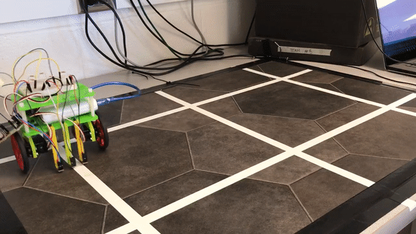
Robot following line and turning left 90º. Robot makes corrections if not straight on the line.
State Machine and Figure Eight
We adapted some of our functions from Lab 1 to get the robot to follow a line and move in a figure eight. To help us do this, we created a state machine:
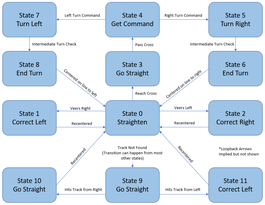
State Machine Diagram.
State Machine Explanation
The state machine’s “default” state is state 0, where it is travelling straight along one of the white lines. From there, it has two basic course correction states, states 1 and 2, which will correct for the robot veering right or left, respectively. These states use functions called correctLeft() and correctRight(), which work by accelerating the outside wheel if it is not already at full speed, or reducing the speed of the inside wheel otherwise. Though the precision of this controller algorithm is limited with the current sensor setup, the correction functions do feature configurable gains that we have used to minimize overcorrection.
Any of states 0, 1, or 2 can transition to state 3, which occurs when the robot reaches a cross in the lines. From here, it will progress directly to state 4, where it stops at the cross. The machine will set a variable high indicating that it is waiting for a command, which currently either tells it to turn right or left, but will also allow the robot to continue straight in later versions. Once the robot receives a turning command, it will proceed to states 5 and 6 for a right turn, or states 7 and 8 for a left turn. The pairs of states contain intermediate conditions that the robot must meet while it makes its turn, including expected line patterns and minimum durations. Once the robot completes either state 6 or 8 and has finished the maneuver, it returns to state 0 to continue straight along the selected path, making course adjustments as necessary.
States 9 through 11 are intended to allow the robot to return to the lines in the case that it is completely off course (all three sensors are seeing a dark surface). They are not currently tuned as well as the other states, but this has not been an issue as the other states have proven completely effective at keeping the robot on the white lines. When starting the robot off of the course, they work with reasonable consistency. They will be further improved in the future for robustness’ sake.
We implemented our state machine using switch statements:
 /******************
 * Path Correction *
 ******************/

void correctionMachine(){
  state = nextstate;
  linePos = getLinePos();
  switch (state){
    case 0:
      // Straighten
      break;

    case 1:
      correctLeft();
      nextstate = (linePos == 1000)? 1 : ((linePos == 4000) ? 3 : 0);
      break;

    case 2:
      correctRight();
      nextstate = (linePos == 3000)? 2 : ((linePos == 4000) ? 3 : 0);
      break;

    case 3:
      correctStraight();
      delay(250);
      nextstate = 4;
      //nextstate = (linePos == 4000)? 3 : 4;
      break;

    ...
  }
When the robot reached an intersection, it turned right and left through methods that changed the speed of the servos:
/******************
 * ROBOT1 Methods *
 ******************/

void turnLeft(){
  rightspeed = 0;
  leftspeed = 0;
}

void turnRight(){
  rightspeed = 180;;
  leftspeed = 180;
}

void halt() {
  rightspeed = 90;
  leftspeed = 90;
}
Through a sequence of four right turns, then four right turns, our robot was able to follow a line and perform a figure eight:
//Variables for figure 8 sequence
int turnsequence[] = {-1, -1, -1, -1, 1, 1, 1, 1};
...
void loop()
{
  if(waitingcommand == 1){
    turncommand = turnsequence[i];
    i = (i == 7)? 0 : i + 1;
    waitingcommand = 0;
  }
  correctionMachine();

  Serial.println(state);

  wheelRight.write(rightspeed);
  wheelLeft.write(leftspeed);
  delay(5);
}
Moving in a figure eight:
Hardware modifications
Throughout this milestone, we made several hardware modifications. We originally placed the sensors too high off of the ground. After testing, we realized that the sensors experienced less noise when they were closer to the surface, so we attached them about 1-2 millimeters from the ground. Our initial design was with a sensor attached each side and one sensor in the back. After testing, we realized that a more practical design would be to have all three sensors in the front to allow for better corrections when the robot goes off of the line and to allow for better sensing of when the robot should turn. With this setup, the two outer sensors could sense when the robot was off of the line and also when it had reached a cross section.
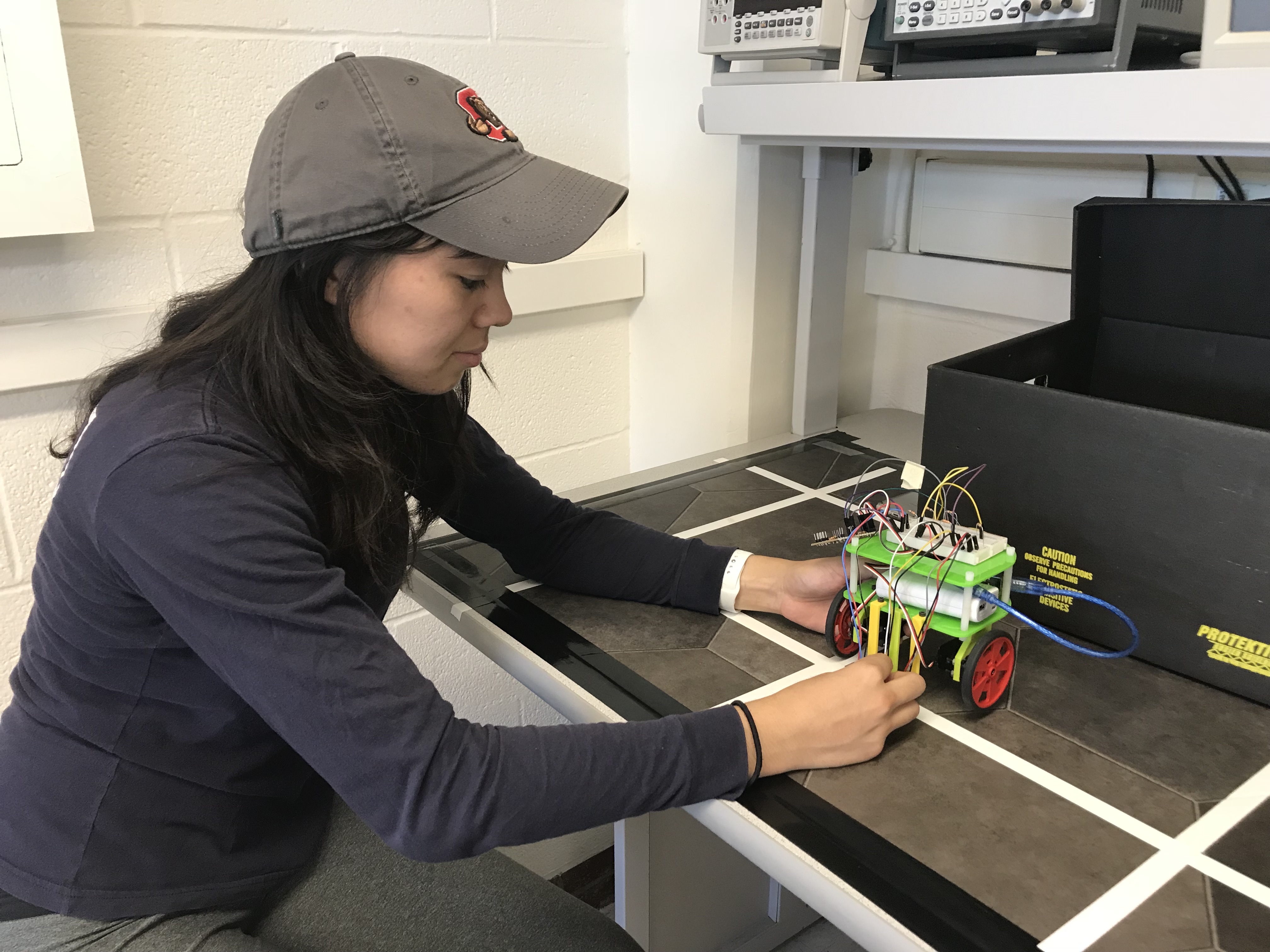
Chloe rewiring the robot.
Roadblocks
During Monday’s lab, we had trouble calibrating our right line sensor. When we exposed it to light and dark surfaces, it outputted the same value. After a lot of testing, we decided to replace the right line sensor with another one. We had no trouble calibrating the new sensor with the same code which means we wasted an hour trying to work with a broken sensor. In the future, we should replace sensors immediately if we notice any problems with them. This can potentially save us a lot of time.

Sidarth and Alex writing line-following code.
Work Distribution
All team members contributed to the completion of this milestone.
- Rebecca worked on this milestone on Monday and Thursday, and wrote line-following logic, wrote a figure 8 implementation, and took team notes/pictures.
- Sidarth worked on this milestone on Monday and Friday, and installed line sensors and other hardware aspects of the robot, found a threshold value for line determination, and filled in any extra work.
- Alex worked on this milestone on Moday, Tuesday, Thursday, and Friday, and created and wrote code for the state machine, calibrated line-following, modified hardware, and exhaustively tested our robot.
- Chloe worked on this milestone on Monday, Thursday, and Friday, and wrote line-following logic, wrote turning logic, and exhaustively tested our robot.