Lab 3
System Integration and Radio Communication
Radio Subteam (Alex and Sid)
We began by hooking up two radios to two Arduinos using jumpers, since we did not have the premade boards available, nor the time to make a temporary breakout board. We tried using the “Getting Started” code provided on the class Github page just to test the basic functionality of the radios, changing their addresses as necessary based on the instructions in the lab. After some tweaking, we were able to achieve successful transmission relatively consistently. We found that reducing the transmission size increased the reliability substantially. At the default 32-byte size, close to 30% of packets were dropped, but at two bytes we did not have any failed transmissions during our testing period. This meant that we had an even larger incentive to reduce our transmission size. At this point, we had learned enough from testing and studying the provided code to start to begin integrating the radios into our design.
We considered was how we might be able to efficiently package the data we send over the radio. Our first consideration was our position in the maze. The final maze will be nine by nine squares, and our first idea was to use four bits for each axis, or eight bits total to represent our position in the grid, which would work sizes up to a 16 by 16 grid. Having a separate variable for each axis means that we need an extra bit (a nine by nine maze has only 81 possible positions, meaning that we could conceivably represent all positions with seven bits instead of eight), but will make calculations on the robot much simpler. If we were to just directly enumerate the squares, we would probably need to do a table lookup each time we moved, rather than simply incrementing or decrementing a coordinate. We were not short on space for the transmission, but the alternative scheme remains an option should we need it for some reason.
The next consideration was for wall positions. The simplest method seemed to be allocating four bits for this, one for each of the possible four walls adjacent to a square in the maze. The bits would correspond to the North, East, South, and West walls, respectively.
Our final consideration, though not necessary for this lab, is treasure locations. We are not yet sure of how exactly the treasures must be identified in the GUI, but we estimate we must allocate at most five bits: two to tell which of the four faces of the square it is on, two for differentiating the three shapes, and one for indicating the color, red or blue. If we do not need to determine which wall face the treasure is on and only the square where it is located, then we could accomplish this with only four bits, which would bring our total transmission size to 16 bits. This means that our transmission could be the size of a short.
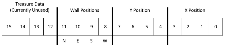
Proposed Transmission Format (Size of Short).
Given this proposed transmission format, the next step was to modify the robot software to actually find these values. With the addition of a right and left facing wall sensor, we had most of the hardware necessary, but additional software features would be required. We will discuss this in greater detail in the integration section.
Robot Subteam (Chloe and Rebecca)
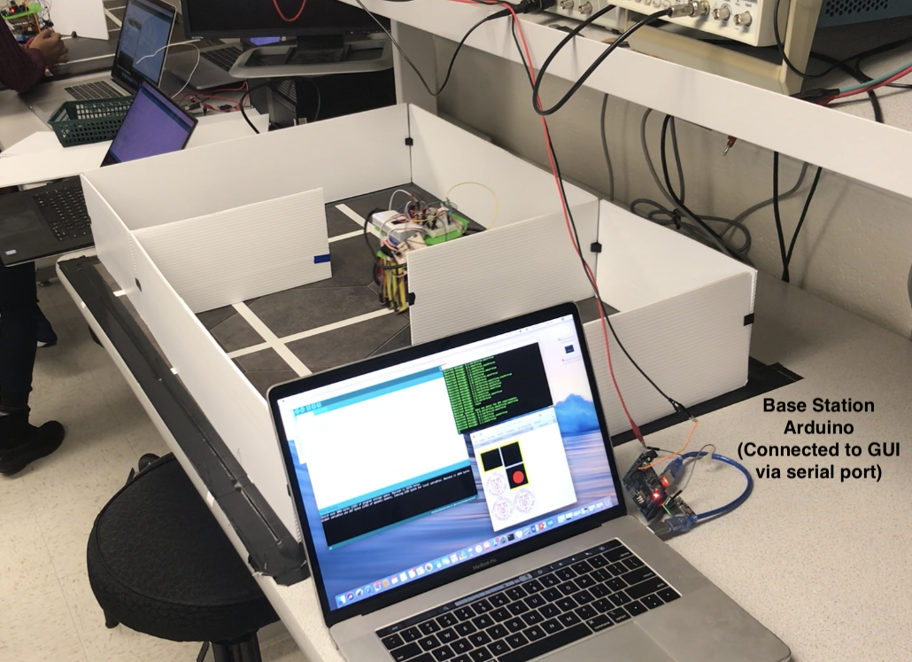
We divided our task into two seperate parts: 1) Creating a Base Station to receive robot data and display on GUI and 2) Modifying our robot’s hardware and software into a single system that allows it to start at 660 Hz, watch for other robots, and ignore decoys.
Base Station and GUI
We downloaded the provided GUI scripts and created tested the example 2x3 maze on the receiver (base station) Arduino.
We wrote a translation method in our base station script that was able to translate a 16 bit integer (that represented data from our robot, in the format described above) into readable String values based on the GUI documentation. The translate() method used bit shifting and other bitwise operations to decode our robot’s information:
/* Translates 16 bit number into valid String value for GUI */

String translate(int telemetry) {
  if (telemetry == 0xFFFF)
    return "reset\n";

  String v = "";

  // x position
  v += ((telemetry & 0x000F));
  v += ",";

  // y position
  v += ((telemetry & 0x00F0) >> 4);

  // walls
  boolean n = ((telemetry & 0x0F00) >> 8) & B1000;
  boolean e = ((telemetry & 0x0F00) >> 8) & B0100;
  boolean w = ((telemetry & 0x0F00) >> 8) & B0001;
  boolean s = ((telemetry & 0x0F00) >> 8) & B0010;
  if (n) {
    v += ",north=true";
  }
  if (e) {
    v += ",east=true";
  }
  if (s) {
    v += ",south=true";
  }
  if (w) {
    v += ",west=true";
  }

  return v;
}
Note: for the “reset” String value that the GUI requires to reset the map, we planned to have our robot send 0xFFFF because 1) This data value corresponds to a map square we cannot encounter (walls on every side, x and y coordinates greater than 9) and because 2) our translate() method only takes in integer values, not Strings.
We tested our translate method by inputting 16 bit (hexadecimal, since Arduino doesn’t allow 16 bit binary values) values and printing out the translated values to the serial monitor:
void loop() {
  // a very basic "2x2 maze" with user inputted data
  Serial.print("reset\n");
  unsigned int telemetry = 0xF900;
  Serial.print(translate(telemetry) + "\n");
  delay(1000);
  telemetry = 0xFC10;
  Serial.print(translate(telemetry) + "\n");
  delay(1000);
  telemetry = 0xF611;
  Serial.print(translate(telemetry) + "\n");
  delay(1000);
  telemetry = 0xF301;
  Serial.print(translate(telemetry) + "\n");
  delay(1000);
}
After ensuring that the translation between a 16 bit integer and GUI was correct, we tested to ensure that the base station could establish a connection (via the radio) to the robot and receive 16 bit numbers. The next step was to combine these two capabilities: allow the base station to listen for telemetry using the radio, and translate that telemetry into proper String formats for the GUI. We did this in a script called radioSend, which is the script we run for our base station.
Robot
Our robot had to additionally avoid decoys, stop when detecting other robots, and start on a 660 Hz tone. Before completely assembling the robot, we began by testing each of our subsystems.
The Arduino has a limited number of analog input pins, so integrating all of the features together (three line sensors, three wall sensors, and two amplifiers for 660 Hz listening and IR sensing) required adding an analog multiplexer. We use two digital pins to select the inputs, where 00 is for a wall sensor, 01 is for the IR amplifier, and 10 is the microphone amplifier.
We integrated starting the robot on a 660 Hz tone with a while loop in our setup:
void setup() {

  while (startRobot < 20) { //Tone detection
    listen660();
    delay(10);
  }

}
And our IR robot sensing inside our main loop:
void loop() {
  ...
  doFFT();
  ...
}
In our previous milestone, we failed to have our robot stop 1 foot from other robots, so an addition we added to this lab was lowering the threshold of our IR reading (by iterative, manual testing, and reading FFT values of when our robot was 1ft (a single square) away from another robot, and stopped our robot accordingly. Additionally, we pointed the IR sensor in the direction our robot was facing, so it would detect only robots in front of it. In the future, we plan to add 3 more sensors so that our robot can detect other robots in all directions.
After integrating both the 660 Hz tone listener, and the IR robot detection onto our robot, we tested that the robot would ignore a decoy (see video near end).
Integration
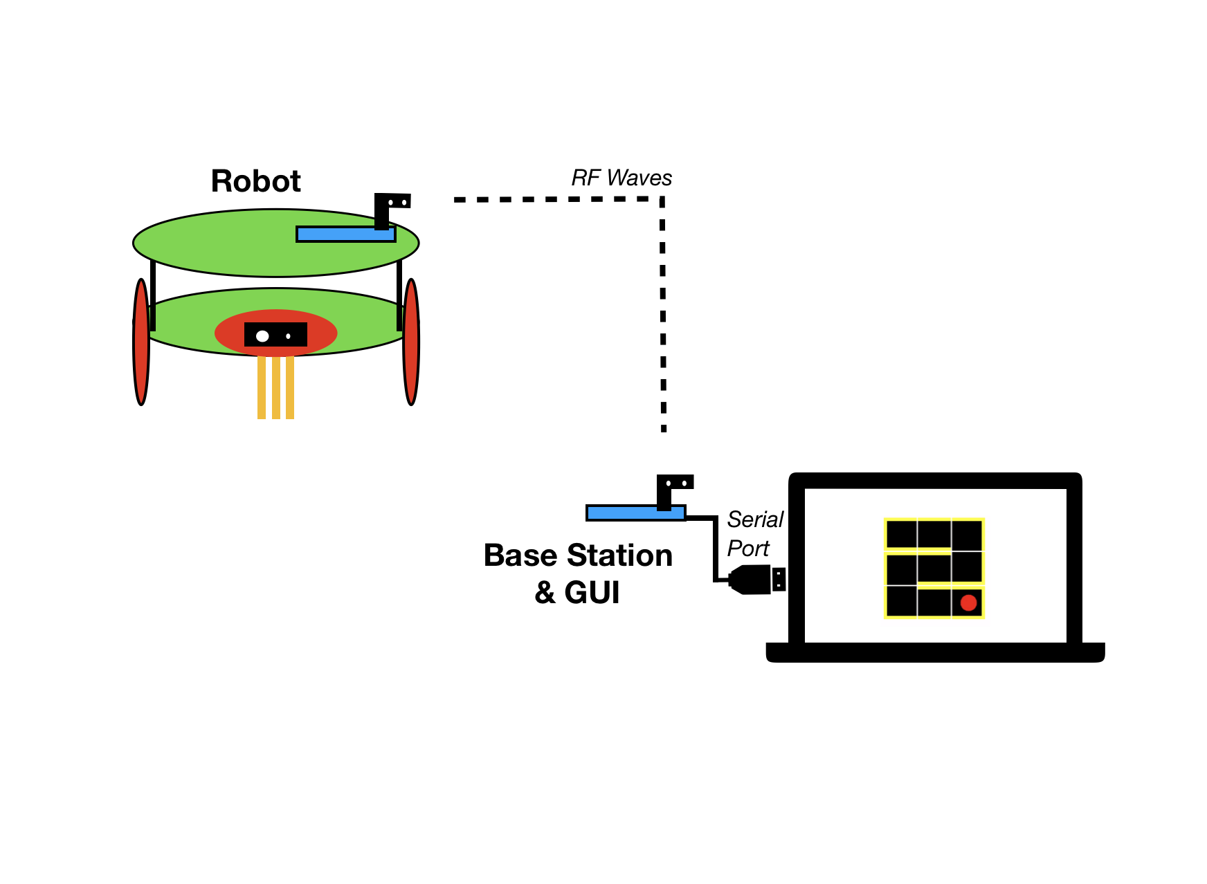
Visual Schematic of Robot Communicating with Base Station and GUI.
The previous version of the robot’s code, while robust enough to navigate simple maze structures and follow lines, did not actually have any concept of its location or orientation; all of the decisions made were from current sensor information. That implementation already used a state machine (now more streamlined) to do its path following and wall avoidance, so our first task was to enhance the robots ability to track its own state using this existing infrastructure.
The first addition made was a variable used to track the robot’s orientation, or which direction it is currently facing. This is done using an integer, which is initially set to a value in the low thousands. In order to determine our orientation, we do a modulus operation on this integer value where a result of 0 indicates we are facing North, 1 is East, 2 is South, and 3 is West. This implementation was chosen because it is so easily integrated with the existing state machine: upon completing a right turn, we increment the orientation variable by 1, and we decrement it on completing left turn.
Next, we needed the ability to track our position. Using the orientation variable, this was a relatively simple task: using a switch statement, we can check which direction we are facing, and upon moving forward we simply increment or decrement the correct position index. These position indices are currently set to zero initially and are global variables.
Determining wall positions is only a moderate logical challenge with the other features in place. We can check all three of our wall sensors as necessary, where the forward facing sensor will indicate a wall in the direction we are oriented towards, the left sensor the wall one position variable less, and the right sensor one position variable more. The way this is actually implemented involves checking how we are oriented, and then essentially assigning each sensor to toggle the appropriate wall bit for that orientation. Finally, upon starting we assume there is a wall directly behind the robot, and that it is facing due East.
byte WP, L, B, R;
  L = (wallvalleft > WALLTHRESHOLD) ? B01 : 0;
  B = (wallval > WALLTHRESHOLD) ? B01 : 0;
  R = (wallvalright > WALLTHRESHOLD + 30) ? B01 : 0;
  WP = (L<<2) | (B<<1) | R ;
//wallval variables are analog wall sensor inputs

//Assign walls
  switch(orientation % 4){
        case 0:
          walls = (B << 3) | (R << 2) | L ; // 1 1 0 1
          break;
        case 1:
          walls = (L << 3) | (B << 2) | (R << 1) ; // 1 1 1 0
          break;
        case 2:
          walls = (L << 2) | (B << 1) | R ; // 0 1 1 1
          break;
        case 3:
          walls = (R << 3) | (L << 1) | B ; // 1 0 1 1
          break;
      }

Robot completing the backwards-S maze and properly updating the GUI:
Storing the Maze
The robot now also has a 9 by 9 byte array representing the maze, which allows it to keep track of which tiles are explored and walls it has already encountered. This is currently not used for anything, but it will become important when we begin implementing exploration algorithms.
All Together
Complete integration of all subparts and our robot completing all required tasks for this lab:
See the latest code our robot is running here.