Lab 2
Analog Circuitry and FFT
Objective
The purpose of this lab is to add sensors to our robot and to make analog circuits and a digital filter to interface with the Arduino. The two sensors are a microphone circuit and an IR sensor. The microphone circuit will detect a 660 Hz whistle blow signifying the beginning of the maze mapping. The circuit with the IR sensor will capture inputs from the sensor to detect nearby robots emitting IR at 6.08 kHz and distinguish them from decoys emitting IR at 18 kHz.
Procedure
We split up into two teams, the acoustic team and the optic team, and progressed through the lab as follows:
Materials Used
The acoustic team used the following materials:
- 1 Arduino Uno
- Electret microphone
- 1 µF capacitor
- 300 Ω resistors
- ~3 kΩ resistor
- Various other components, as needed
The optical team used the following materials:
- 1 Arduino Uno
- IR transistor (OP598)
- 1 IR hat
- 1 IR decoy
- Various other components, as needed
Acoustic Team (Sid and Chloe)
Assembling the Microphone
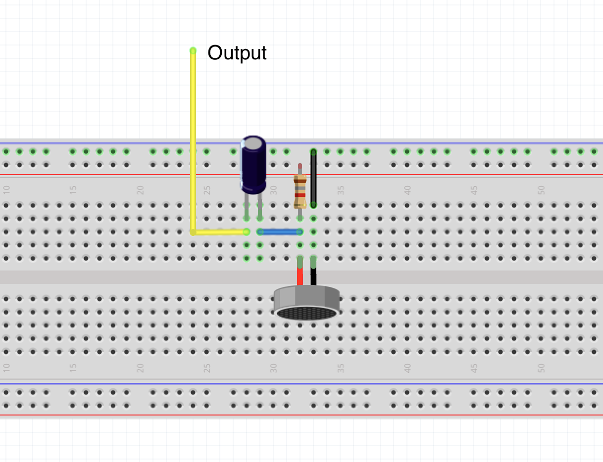
Our first step was assembling the basic microphone circuit on the lab 2. The output of the circuit went to analog input A0. Our circuit was assembled according to the lab instructions:
Microphone circuit schematic.
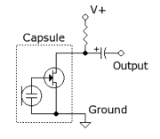
Microphone circuit diagram. Source: here
Using FFT Library
Next, we added the Open Music Lab FFT library to our Arduino IDE. We then the example script fft_adc_serial. In short, fft_adc_serial processes the signal into pin A0 using an FFT and sends it over the serial port.
The FFT algorithm samples a signal over a period of time and divides the signal into its frequency components. In this case, the signal is range of voltages into analog pin A0. Below is the graph when we generated a 660 Hz tone using an iPhone app into the microphone circuit.
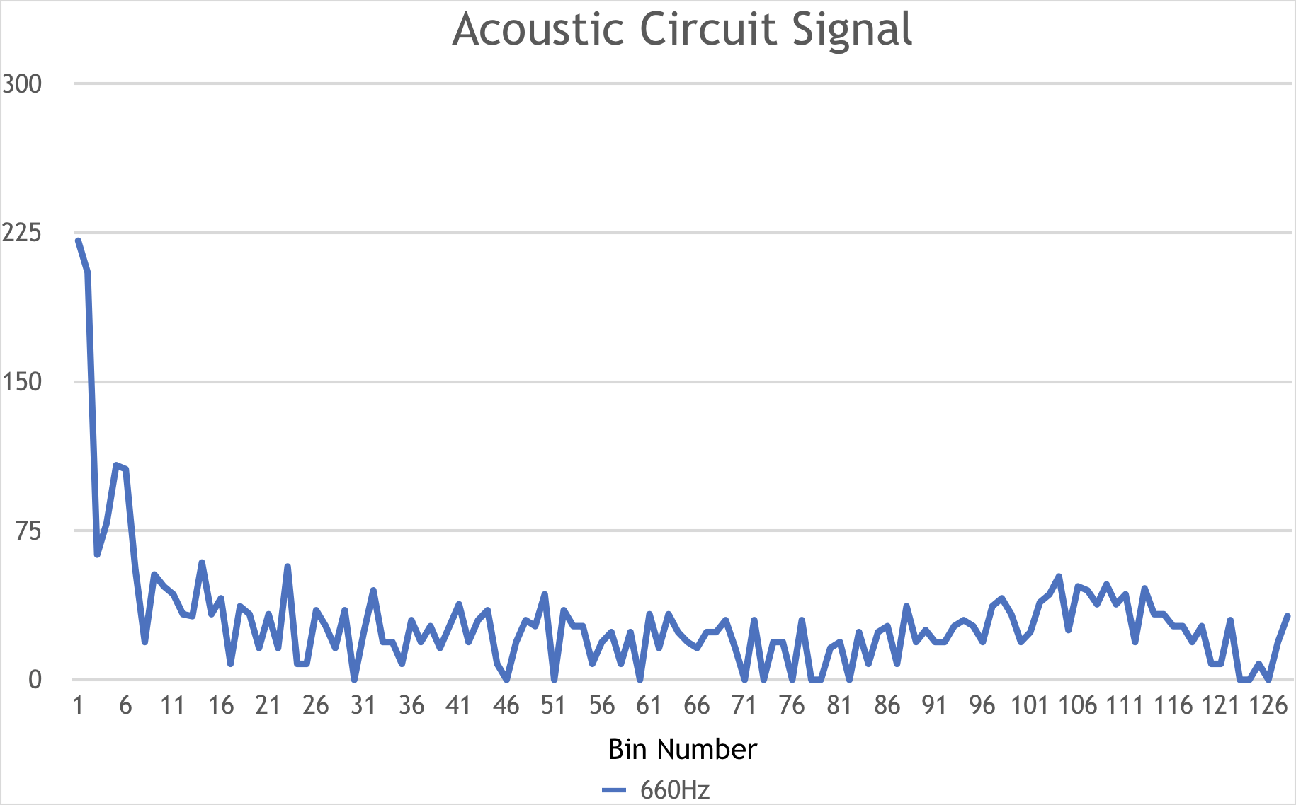
FFT output when playing 660 Hz. Peak in bin 5, other peaks likely due to surrounding lab noise.
Amplifying the Signal
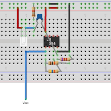
We decided that we wanted to amplify the signal so it would be readable. We added a filter and an op-amp (LF 353) to produce a gain of approximately 100. We calculated this with resistor values of 380kΩ and 3.8kΩ:
Vout = Vin(1+R2/R1) Vout/Vin = 1+R2/R1 = 1 + 380kΩ/3.8kΩ ≅ 100

Microphone circuit schematic with amplifier.
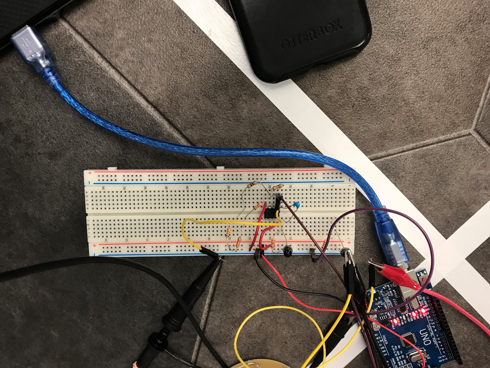
We first tested our amplifier using the function generator to input a 660 Hz frequency to ensure we got a gain (compared to the circuit without the amplifier), then reassembled the circuit to include the microphone.

Completed amplified circuit with microphone.
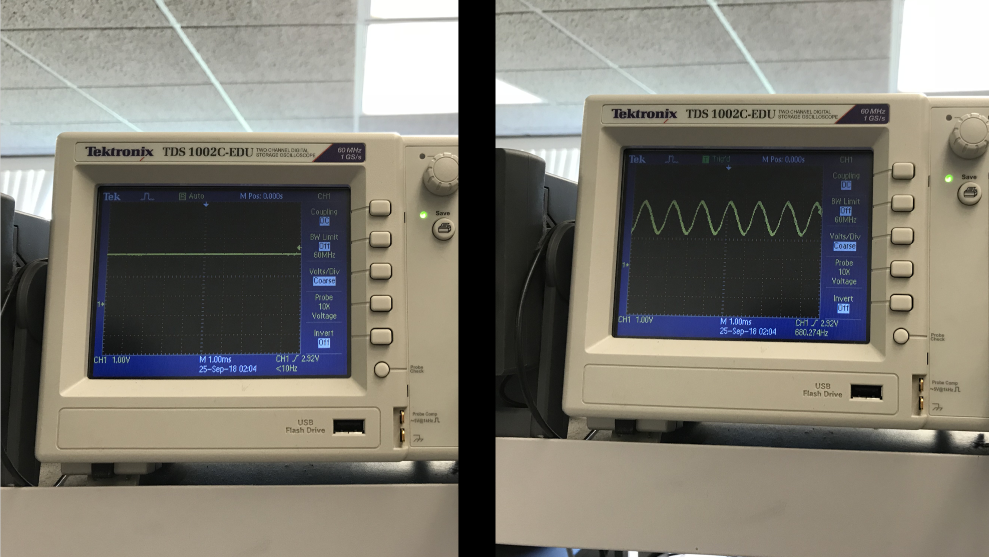
Reading output of a 660 Hz frequency (from the function generator) of our circuit, with and without our built amplifier.
Distinguishing the 660 Hz Tone
After ensuring the output signal of our circuit could be read by the ADC with an amplifier in place, we ran the fft_adc_serial script. To generate the correct frequency, we used an iPhone app that played a 660 Hz tone. We plotted the FFT of a 660 Hz generated tone into the microphone, and the FFT of no tone into the microphone and found the following results:

FFT on the signal of our acoustic circuit, with 660 Hz and no tone as input frequencies.
Despite the fact that there was talking in the background when we plotted our “no tone” frequency, there is clearly a difference in the output in bin 5. Thus, we’re able to find a threshold value to distinguish the 660 Hz tone from the “no tone.” We picked 110 (based on our FFT plots) as our threshold. In our fft_adc_serial, we added the following logic to turn on the LED when the 660 Hz tone was picked up by the microphone.
void loop() {

  while(1) {
    ...
    for (int i = 0 ; i < 512 ; i += 2) {
      ... // put data in bins
    }
    ... // process data

    /* Distinguishable tone logic:
     * Based on our FFT plots, if value is >= 110 in bin 5, a 660Hz tone is heard.
     * 110 is our threshold value for background noise.
     */

    if (fft_log_out[5] >= 110) {
      digitalWrite(LED_BUILTIN, HIGH);
    }
    else {
      digitalWrite(LED_BUILTIN, LOW);
    }
  }
Demonstration of 660Hz tone:
IR Team (Rebecca and Alex)
Assembling the IR Circuit
To begin, we followed the same steps as above to make sure the FFT code was working. We used a phototransistor to detect the IR hat. Under light, a phototransistor allows current to pass, meaning it acts like a closed switch. When there is no light, it does not let current pass, meaning it acts like an open switch. We created the following circuit to test the phototransistor.
![]()
Phototransistor circuit diagram.
When we held the IR hat near the phototransistor, we got the following output:

IR output.
We then ran the fft_adc_serial code as described above. The output was not very clear, so we built the following amplifier:

Amplifier diagram.
Amplifier schematic.
Amplifier build.
We used the following resistor values to make our circuit:
R1 = 1.8 kΩ
R2 = 6.71 kΩ + 482 Ω = 7.192 kΩ
R3 = 6.72 kΩ + 3.25 kΩ = 9.97 kΩ
R4 = 46.3 kΩ
C1 = 3.3 nF
This gives us a gain of Av = 1 + R4/R3 = 1 + (46.3 kΩ/9.98 kΩ) = 5.64 We then used the FFT function on the oscilloscope to test our amplifier. There is a large peak in the middle, which represents the frequency we are trying to amplify.

Amplified frequency with FFT function.
We then used the fft_adc_serial code to process the signal with the amplifier in place. To calculate the bin number we need to look at, we found the bin width from ((16 MHz/32 prescalar)/13 clock cycles)/256 bins, which equals a bin width of approximately 150 Hz. Then, we divided the desired frequency (6.08 kHz) by the bin width (150 Hz) to get the bin number, which is approximately 42. This means that the important bin to look at is bin 42.

FFT plot with amplified IR circuit. Peak in bin 42.
From this graph, bin 42 has a larger amplitude than the surrounding bins. The other peaks are due to other light in the room that is being picked up. We then updated the ffc_adc_serial code to turn on an LED when the IR is being detected. To do this, we set a threshold value of 45 and looked at bin 42. When the value of bin 42 was above 45, we turned the LED on and when the value of bin 42 was below 45, we turned the LED off.
...

if (fft_log_out[42] >= 45 {
  digitalWrite(LED_BUILTIN, HIGH);
}
else {
  digitalWrite(LED_BUILTIN, LOW);
}
In the future we may want to tweak this threshold value based on how it is performing, and the addition of some kind of averaging will likely also be necessary to make sure we do not falsely detect the position of another robot.

The Arduino detecting the presence of the IR emitter. The LED on the Arduino lights up to indicate this.
Single System - Putting it all together
After the Acoustic Team distinguished a 660 Hz tone from background noise, and the IR Team distinguished a 6.08kHz IR signal from an IR signal at 18kHz, we combined code which would allow our robot to do both audio and IR. We decided to light up the built-in LED on the Arduino whenever a 660 Hz tone was sensed (and turn it off when there was just background noise), and light up an external LED on pin 8 when a 6.08kHz IR signal was detected (and turned it off when 18kHz was detected). In our fft_adc_serial, we wrote:
...

/* Acoustic Team's logic */
if(fft_log_out[5] >= 110) {
  digitalWrite(LED_BUILTIN, HIGH);
}
else {
  digitalWrite(LED_BUILTIN, LOW);
}

/* IR Team's logic */
if(fft_log_out[42] >= 45) {
  digitalWrite(8, HIGH);
}
else {
  digitalWrite(8, LOW);
}