Lab 1
Microcontrollers
Objective
The main goal of this lab was to learn the basic functionality of the Arduino Uno and the Arduino IDE. The focus of the first several parts of the lab are to write programs using the Arduino IDE to control LEDs and servos. The last part of this lab focused on putting together the beginning of our robot and getting it to move.
Procedure
We split up into two groups of two for this lab. Both groups progressed through the lab as follows:
Materials
- 1 Arduino Uno
- 1 USB A/B Cable
- 1 Continuous rotation servos
- 1 Pushbutton
- 1 LED
- 1 Potentiometer
- Several Resistors in the kiloohms range
- 1 Solderless breadboard
Part 1: Communicating Between the UNO and IDE
For this part of the lab, we used the “Blink” example code to learn how to program the Arduino. The example blinks the built-in LED on the UNO when run. The code used was:
// the setup function runs once when you press reset or power the board
void setup() {
  // initialize digital pin LED_BUILTIN as an output.
  pinMode(LED_BUILTIN, OUTPUT);
}
// the loop function runs over and over again forever
void loop() {
  digitalWrite(LED_BUILTIN, HIGH);   // turn the LED on (HIGH is the voltage 	level)
  delay(1000);                   	// wait for a second
  digitalWrite(LED_BUILTIN, LOW);	// turn the LED off by making the voltage LOW
  delay(1000);                   	// wait for a second
}
Part 2: Modifying the Blink Sketch
We first placed an LED and resistor on a breadboard and connected the LED to pin 2 on the UNO. Next, we modified the existing “Blink” code to work for an external LED. To do this, we declared the variable ‘redled’ to specify the pin we wanted to blink instead of using the global variable LED_BUILTIN like we did in the previous section. Our code is as follows:
// the setup function runs once when you press reset or power the board
int redled = 2;
void setup() {
  // initialize digital pin LED_BUILTIN as an output.
  pinMode(redled, OUTPUT);
}
// the loop function runs over and over again forever
void loop() {
  digitalWrite(redled, HIGH);   // turn the LED on (HIGH is the voltage level)
  delay(1000);                   	// wait for a second
  digitalWrite(redled, LOW);	// turn the LED off by making the voltage LOW
  delay(1000);                   	// wait for a second
}

Blink Sketch: Circuit Diagram

Part 3: Analog Output
In part 3, we used pulse width modulation (PWM) to change the brightness of an LED. PWM works as follows: to get 50% brightness, for example, the Arduino writes a high value to the LED for 50% of the duty cycle, then a low value for the remaining 50% of the cycle to average a 50% brightness.
The LED’s brightness depended on our potentiometer’s value. Since potentiometer values run from 0 to 1023 and LED values run from 0 to 255, we used the map function to scale our potentiometer reading to a number between 0 and 255.
We connected an LED to pin 3 and potentiometer to pin A0. We were able to see the various range of potentiometer values by using the Serial.println() function in our code, then by looking at the serial monitor on the Arduino IDE.
int pot = A0;
int potValue = 0;
int analogLED = 3;
int outputValue = 0;
//min:102 max: 1023
void setup() {
  // put your setup code here, to run once:
  pinMode(analogLED, OUTPUT);
  Serial.begin(9600);
}
void loop() {
  // put your main code here, to run repeatedly:
  potValue = analogRead(pot);
  Serial.println(potValue);
  outputValue = map(potValue, 0, 1023, 0, 255);
  analogWrite(analogLED, outputValue);
  delay(2);
}

Analog Output: Circuit Diagram
Part 4: Parallax Servos
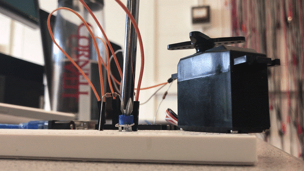
In this part of the lab, we connected a servo to pin 6. We used the Servo library and a built-in example to program the servo. Once we got that to work, we used our potentiometer to change the speed of the servo.
#include <Servo.h>

int PINNAME = A0;
Servo myservo;
int pos = 0;
void setup() {
  myservo.attach(6);
  pinMode(PINNAME, INPUT);
}

void loop() {
  myservo.write(map(analogRead(PINNAME), 0, 1023, 0, 180));
}

Parallax Servos: Circuit Diagram
Part 5: Assemble and Run Robot
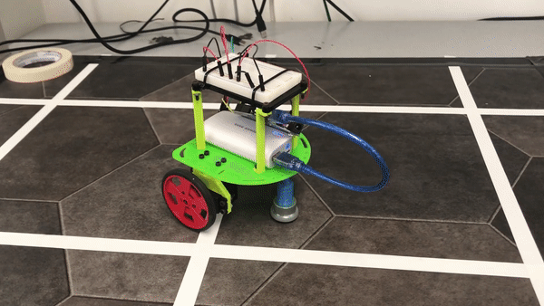
First, we assembled the robot using a chassis, screws, a 9V battery with a clip, servos, wheels, and ball bearings. We attached two servos to wheels and mounted the servos and ball bearing to the chassis. Below is a circuit diagram and image of our assembled robot.
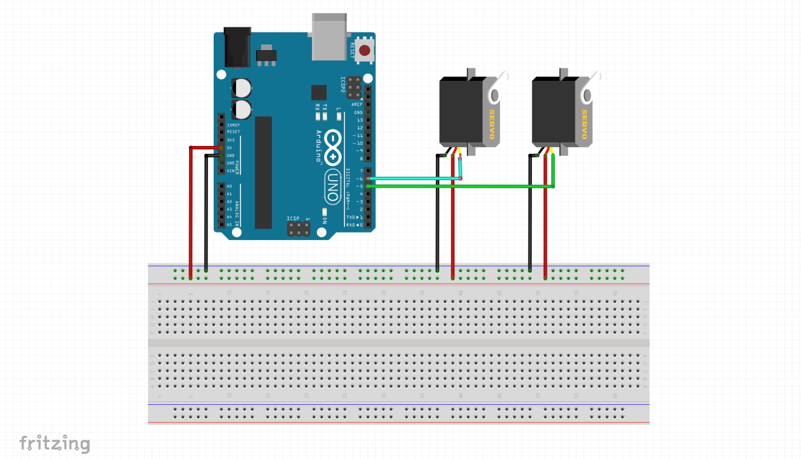
Completed circuit diagram of robot for lab 1. The two servos are used as motors for each wheel.
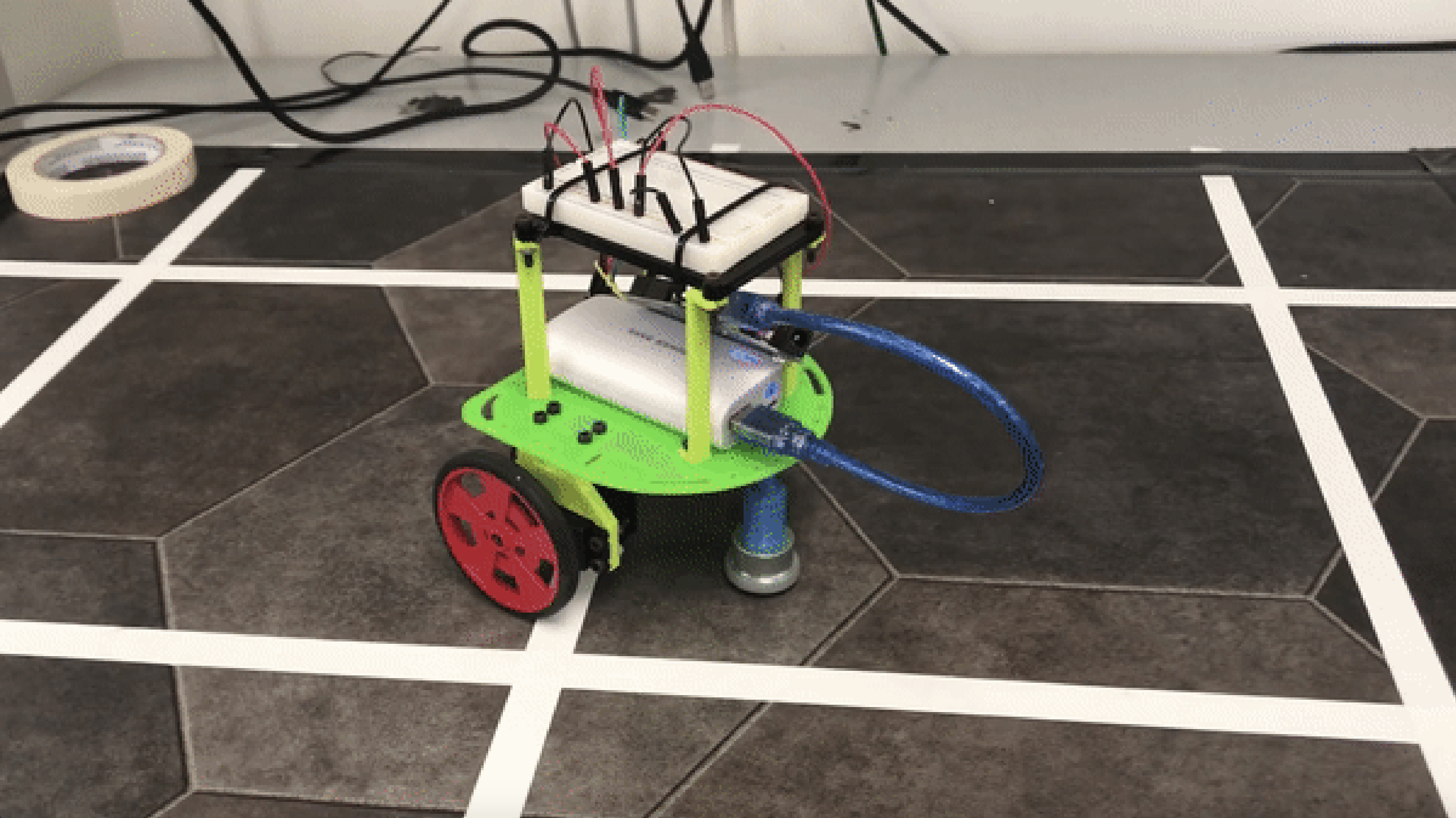
Assembled robot.
Once the robot was assembled, we hooked it up to an Arduino and wrote functions for it to drive forwards, backwards, turn, drive in a square, and drive in a figure eight. We used code from the previous part of the lab to program the servos to make the robot move. The following code is how we set up the servos and initialized variables:
#include <Servo.h>
Servo wheelA; // right wheel when moving away from you
Servo wheelB; // left wheel when moving away from you

int clockwiseA = 0;
int counterclockwiseA = 180;
int clockwiseB = 180;
int counterclockwiseB = 0;
int halt = 90;

void setup() {
  Serial.begin(9600);
  wheelA.attach(5);
  wheelB.attach(6);
  pinMode(heartbeat, OUTPUT);
}
After setting up the servos, we wrote code to make the robot move forwards and backwards:
void forwards(int side) {
  wheelA.write(clockwiseA);
  wheelB.write(clockwiseB);
  delay(side);
}

void backwards(int side) {
  wheelA.write(counterclockwiseA);
  wheelB.write(counterclockwiseB);
  delay(side);
}
We then wrote code to make the robot turn:
void turn(int speedA, int speedB, int delay1) {
  wheelA.write(speedA);
  wheelB.write(speedB);
  delay(delay1); // amount of time to turn 90 deg
}
Next, we used the forwards and turn functions to make the robot move in a square:
void squareRight(int side) {
  forwards(side);
  turn(counterclockwiseA, clockwiseB, 800);
  forwards(side);
  turn(counterclockwiseA, clockwiseB, 800);
  forwards(side);
  turn(counterclockwiseA, clockwiseB, 800);
  forwards(side);
  turn(counterclockwiseA, clockwiseB, 800);
}
The following code is the functions we wrote and the code that was used to make the robot move in a figure eight:
void figureEight(int side, int turnSide) {
  turn(clockwiseA,90,turnSide);
  forwards(side);
  turn(90,clockwiseB,turnSide);
  forwards(side);
}
For each task, we called the function for the respective task in the main function, loop() and our freeze and quit functions to get the robot to stop moving. Here is the figure eight function being called:
void loop() {
  figureEight(2000,3600);
  quit();
}

void freeze() {
  wheelA.write(halt);
  wheelB.write(halt);
}

void quit() {
  while (true) {
    freeze();
  }
}
Robot moving in a figure 8.