Final Robot Design
What our robot can do
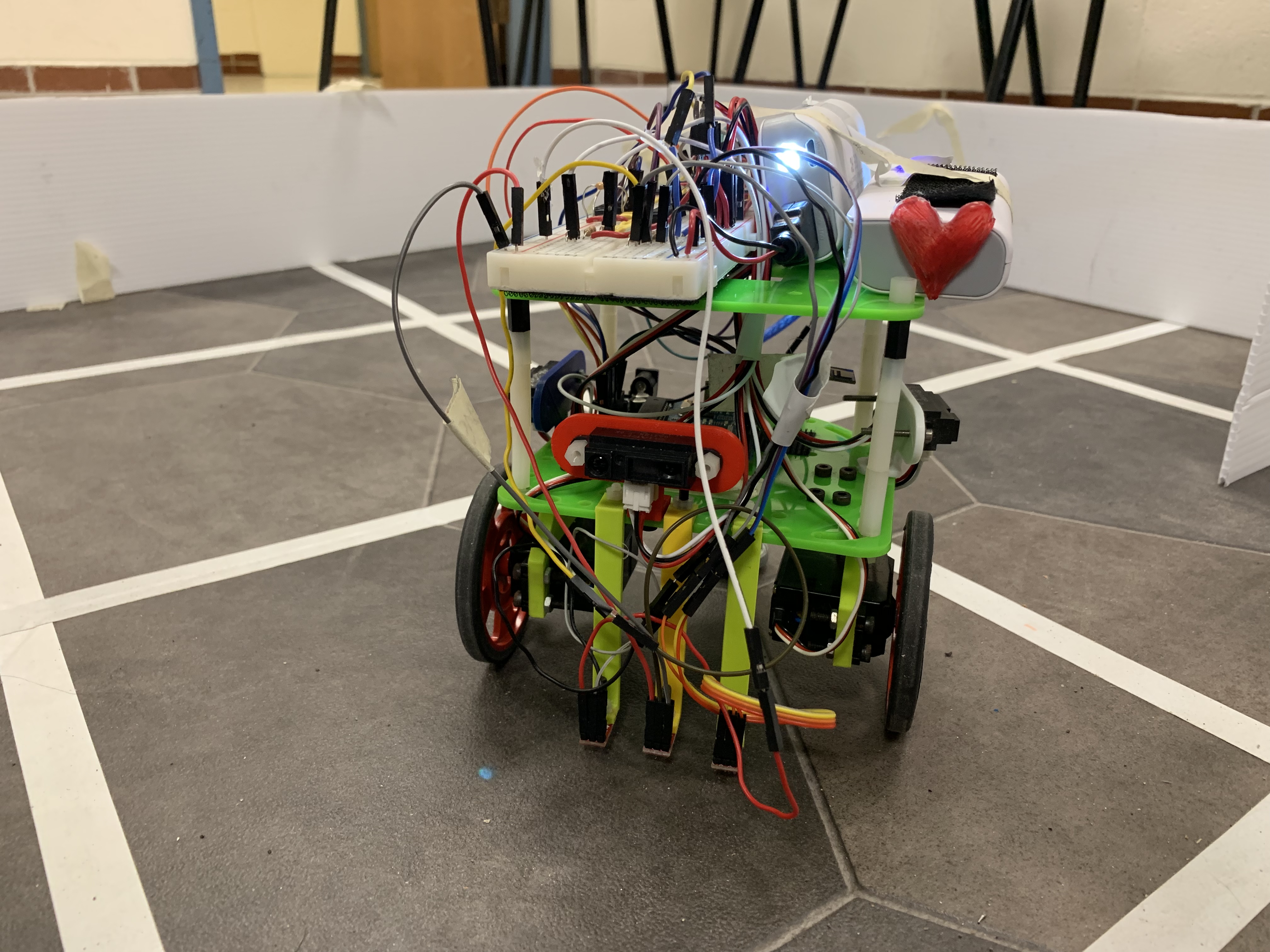
Our Finalized Robot
Throughout the Fall 2018 semester, we created a robot that could:
- Navigate a maze
- Start when a 660 Hz noise is detected
- Use sensors to follow lines and detect walls
- Avoid other robots using IR detection
- Use depth first search and path planning algorithm to determine how to navigate through the maze
- Communicate using radios to update a GUI
- Detect treasures using image processing
Our final robot cost: $86.00
- Pololu Line Sensors (3 @ $3.00): $9.00
- Short Range IR sensors (3 @ $7.00): $21.00
- Camera: $14.00
- Parallax servos (2 @ $13.00): $26.00
- Arduino Uno: $16.00
Our robot’s software is open source code!
Modifications to Robot Design
Beyond the baseline requirements from the labs and milestones required in class, we made several improvements to our robot so that it would have the best chance when competing against other robots in the final competition. We document these additions and improvements in this section.
Better Maze-Solving Algorithm
The final robot code had several main sections. Here, we will discuss the sections directly relevant to maze solving and locomotion.
We used the servo library to interface with the servo motors attached to the wheels. In all the labs before competition, our robot had a single state machine that would continuously dictate how the robot should move. It would line follow as it traveled straightaways, and would pause very briefly at intersections to ping another section of the code in order to receive instructions for how to proceed at the intersection: go straight, turn left, or turn right. How these instructions were actually generated depended on the lab: for the figure eight the instructions were hardcoded, and for wall following it would ping a function that would poll the line sensors to return the appropriate action command. This setup of a state machine calling all of the shots, and briefly yielding control for instruction at intersections, worked quite well at intersections. The issues with this method arose when we began implementing more complicated maze searching algorithms; the old state machine was basically the main code, and other functions were called asynchronously by it, making it very hard to provide a sequence of instructions rather than one instruction at a time.
For the final competition code, the old state machine controlling the robot was, for the most part, scrapped entirely, and replaced by three motion related functions: one which would move the robot forward to the next intersection, one which would turn it 90 degrees left, and one which would turn it 90 degrees right. The forward motion functions used three line sensors at the front of the robot to stay on course and detect the intersection that would end the motion, but the turning functions were entirely timing based, as we found this to be much more consistent than other methods and ultimately fine since the forward motion function would immediately correct any small inaccuracies. These three functions were the core of the robots motion commands for the final maze code, since more complicated motion functions could be built by chaining them together.
Next, the robot had a number of data structures and state variables to keep track of itself in the maze. It had two variables representing its coordinates, x and y, in the maze, and an orientation variable, which tracked whether it was facing North, East, South, or West, and would be adjusted accordingly during a 90 degree left or right turn. By checking which way it was facing, the robot would know which coordinate to adjust when it moved forward. For example, when facing East, a forward move would correspond to an increase in the x coordinate. We also had a nine by nine maze array, which kept track of whether squares were visited, and also which walls were detected adjacent to that square (on the North, East, South, and West faces of the square).
This leads into the next section, which used the wall sensors. The robot had a forward facing, left facing, and right facing wall sensor, each of which would be checked at every intersection. These would correspond to universal directions in the maze array; that is, if the robot was facing East, then the left wall sensor would correspond to the North wall, the forward sensor to the East wall, and the right sensor to the South wall. These wall sensors would be polled several times, averaged, and have their information processed in a getTurn() function.
Finally, we had a basic array stack with push() and pop() methods associated with it, necessary for the final algorithm. These are the main building blocks for our maze searching system. In order to see how they work together to actually achieve exploration, first consider the getTurn function, which is the first function called. When the function is called, the wall sensors are polled on the front, left and right. The robot can see eight possible configurations of walls in front of it at any given moment, pictured below:

Possible wall configurations visible to the robot at a square
The robot had two modes, essentially, while searching the maze. First, it had a basic exploration mode, which works as follows. Based on each of these configurations of walls, there are different directions that the robot can possibly travel, denoted by the orange arrows.

The travelable directions at a square based on the walls surrounding it
In exploration mode, the robot will simply act on a square-by-square basis, looking at the possible directions it can travel. As it does so, it will check the maze array to see whether available adjacent squares (that is, squares not blocked by walls) were already visited. It would prioritize visiting squares it had not already visited, typically with the priority level of forwards, left, and right as applicable. Based on the output of the getTurn function, the motion functions could be called to achieve the appropriate robot action. Each time the robot moves forward in this mode, it pushes the location it travels from to the stack, creating a “breadcrumb trail” back along the path that it took. If no traversable adjacent squares are unvisited, the robot switches into its second mode, backtracking. In this mode, the robot would begin popping tile locations from the stack and travelling to that location; since all locations in the stack are adjacent to each other, this was a relatively simple logical task. Below is the code for traversing to an adjacent tile, and the if statement for the case where the robot is currently facing North. Corresponding conditional statements follow in the full code for cases where the robot is facing any other direction:
byte temp = pop();
    byte xgoal = (temp & B00001111) - xpos;
    byte ygoal = (temp >> 4) - ypos;

    if(xgoal == -1 && ygoal == 0){
      //move west
      switch(orientation % 4){
        case 0:
          moveRobot(LEFT);
          break;
        case 1:
          moveRobot(LEFT);
          moveRobot(LEFT);
          break;
        case 2:
          moveRobot(RIGHT);
          break;
        case 3:
          break;
      }
      moveRobot(FORWARD);
    }
Each time the robot backtracks to a new square, the getTurn function is called again to determine if there are any unvisited squares along the backtracked path. If there are, then getTurn will override the backtracking, switch back to the exploration mode, and have the robot travel to that new unexplored square. From there, it would again continue in the exploration mode until it again had no adjacent unvisited squares to visit. This method was used to successfully explore a number of large mazes, including some nine by six and nine by seven test mazes in well under the five minute limit.
Mechanics
While iteratively testing our robot in the maze, we learned several things about the mechanics of our robot that caused inconsistency in maze-solving from trial to trial.
One of the biggest issues was that our robot was a little bit top heavy from the two batteries and large breadboard that we initially placed on its top tier. The top-heaviness of our robot posed the issue of tipping over because the robot often would have to make sharp 90° turns and there was high probability of collisions with other more robust robots. Our solution was to add more weight towards the bottom of our robot with the batteries that were already on board. We were going to add additional weighted plates, but our robot seemed robust enough after this fix.
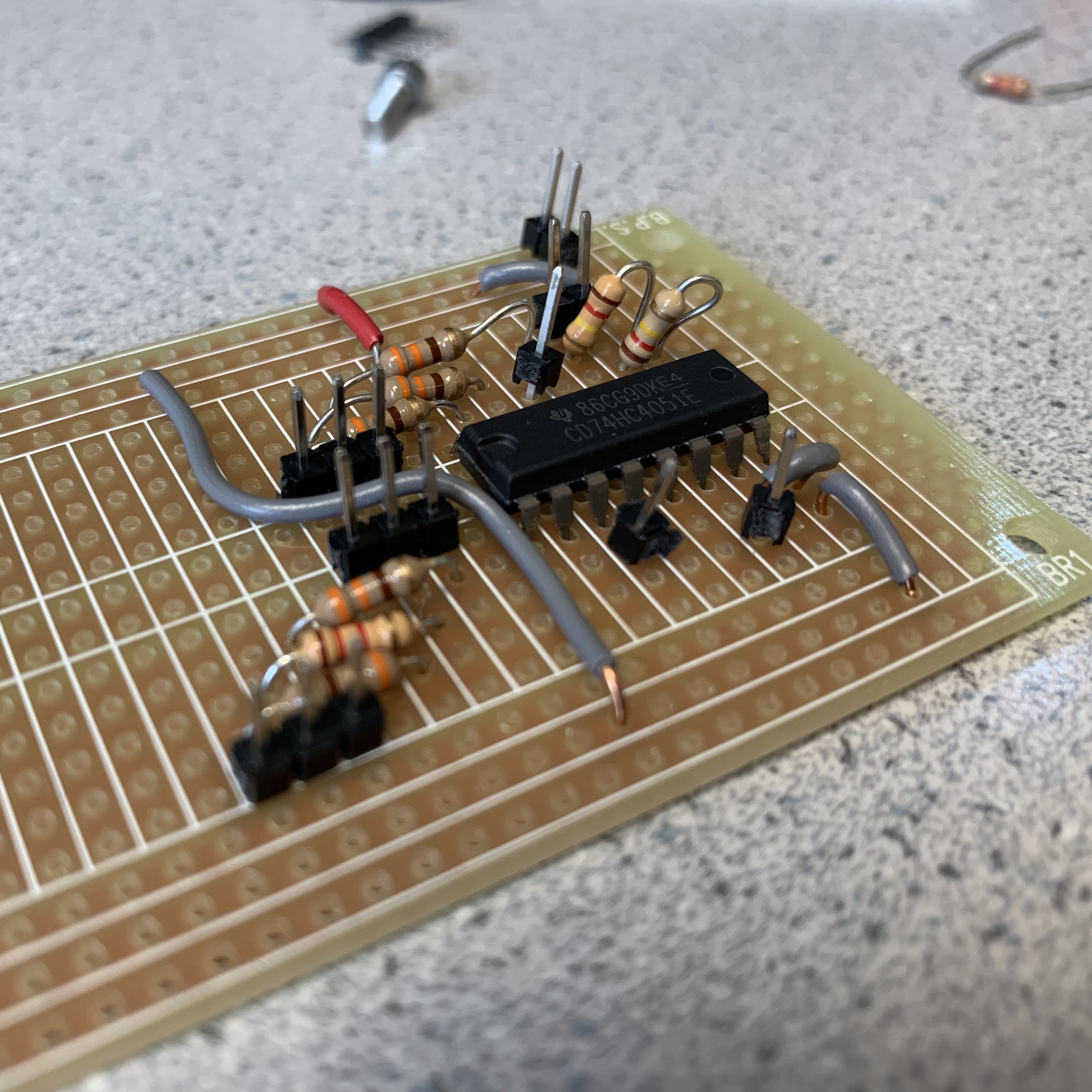
To even further lighten the weight of the robot’s top tier, we rebuilt half our breadboard circuit onto a perfboard, and started building the other half onto another perfboard that would be a shield that seamlessly snapped onto the top of our Arduino. Despite the fact that we did spend time remaking the circuit on these perfboards, they never replaced the breadboard and make it onto our actual robot. We were on tight time before the competition, and chose to spend more of our efforts writing better software for our robot. We were also concerned that placing the perfboards 1-2 nights before the competition was too risky because it didn’t give us a lot of time to figure out why some wiring might have gone wrong. Thus, we would have loved to see our robot more wire-free, but simply ran out of time.
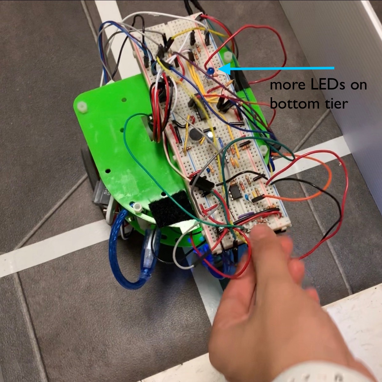
Original (and final) breadboard circuit:

Perfboard circuit intended to replace breadboards:
Another mechanical adjustment we made was to our line sensors. Our line sensors sometimes got loose on our robot, which created two issues 1) inaccurate line sensing due to changed proximity from the ground and 2) fall low enough and drag on the maze, and sometimes get caught causing immobility of entire robot.
To remedy these issues, we moved the line sensors a few millimeters higher than they were, and tightened the screws that held them in place. Moving the line sensors even the smallest bit higher, however, completely changed the thresholds we initially coded into them. We had to iteratively test differences from white lines and black tiled mats and adjust the thresholds in our code accordingly. While our line sensors seemed to never quite work as well as they used to due to various lighting changes, rough spots on the mat, and changed threshold by us, they were able to sense the white lines relatively well.
Robot Speed vs Searching Algorithm Tradeoff
Before we produced an improved path planning algorithm, one of our earlier thoughts was to work on improving the speed of our robot. The idea was that we could just keep our simple maze-searching algorithm because increasing our speed would allow the robot to traverse through the maze more quickly and cover more ground, and because increasing the speed didn’t initially seem difficult. However, we encountered many problems.
We were able to increase the speed of our robot by replacing our wheels with ones of larger diameter. While relatively easy to do, we also had to lower the line sensors because they sat higher with the new, larger wheels. With this, our line sensing was now not calibrated and had to be precisely re-calibrated, which took a long time due to their sensitivity. Additionally, our controls algorithm was flawed with larger wheels, as the robot sometimes couldn’t make quick enough corrections with its quicker speed.
Testing robot with larger wheels–uncalibrated controls and general faultiness:
While we recognized that we should have used larger wheels from day 1, re-writing and calibrating our robot’s algorithm was difficult in the short amount of time during the competition. We also figured that covering more ground in a short amount of time may have caused more collisions with other robots, and that our robot would be better off solving the maze more efficiently rather than more quickly. We switched our wheels back to the original, smaller ones, and wrote an improved maze-searching algorithm, which we describe above.
Debugging
We added LED indicators so that while our robot was driving we could tell what state it was in. We used LEDs to verify the following:
- Wall sensing (also meant robot was at new location)
- Robot detection sensing
- Line correcting
- Entire maze searched
Camera and FPGA Integration
Nearing towards the final competition, our robot did not have our FPGA and camera integrated into its system, despite the fact that our camera with FPGA was properly detecting color and shapes. Integration into our robot’s existing code was proving difficult, and our robot was running low on physical mounting space. We thought our time was better spent on writing a better searching algorithm, and ensuring that basic line sensing and wall-avoidance was working on our robot from previous changes. We anticipated that we would be able to mount the camera with some degree of success, but simply didn’t allocate enough time for us to wrap our heads around as to why it was not working.
Ideas for Future Improvements
With deadlines quickly approaching, it was difficult for us to implement everything we had originally envisioned onto our robot. Here, we list several improvements that we would have liked to seen on our robot during the competition:
- Schmitt trigger circuit to make line sensors digitally output. Our line sensors were analog sensors, but we always desired to use or build digital ones. We wrote out plans to build Schmitt triggers to convert the line sensors’ analog inputs to digital output signals. We would not have had to program thresholds, and would have saved 3 analog pins if this were the case. We envisioned using potentiometers to dial our line sensors’ sensitivity.
- Averaging our fft output for 660Hz. When we amplified our fft microphone circuit and picked a threshold value to get our robot to start on the continuous 660Hz tone, we found that using a threshold value was simply not accurate enough, because our robot picked up external background noise and interpreted it as the correct frequency. So, we would have liked to have programmed our robot such that it would pick samples of sound within a time frame, and average them to see if the signal was correct.
- Less sensitive, but more accurate IR robot sensing. We set our IR sensor’s threshold to be very sensitive just in case we were going to collide with another robot, but sometimes, our robot accidentally read its own IR hat and believed it was seeing another robot. We unfortunately found this out during the final competition, when our robot reached a “dead end,” and our own IR sensor detected our own IR hat because our hat had bounced off of the walls, and our sensor was at a very low threshold. See the video below for evidence of this. To eliminate this problem, we should have programmed our robot to not have done our IR sensing if there was a wall in front of it. If this were the case, there would not be a robot in front of ours anyways, and the IR hat wouldn’t bounce off the walls.
Final Competition
See how our robot did in the final competition!